LASER EXPOSURE WARNING:
The transmitter emits invisible laser radiation. AVOID DIRECT EXPOSURE TO LASER. Never operate the unit with a broken fiber or with a fiber connector open or disconnected. Never work on the optical connections with the equipment power attached. This unit has redundant power. BOTH supplies must be powered down.
SETUP INSTRUCTIONS:
Z-Light Fiber Transmitters ship with preconfigured settings to match the 20dBmV input signal requirement. No additional changes are required on the unit other than following the instructions below.
-
Secure the transmitter to a 19" rack mount using the included screws.
-
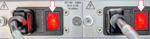
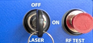
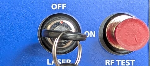
Prior to connecting any cabling to the transmitter, ensure that the two rear power supply switches are switched off and that the keyed laser switch on the front panel is switched off.
-
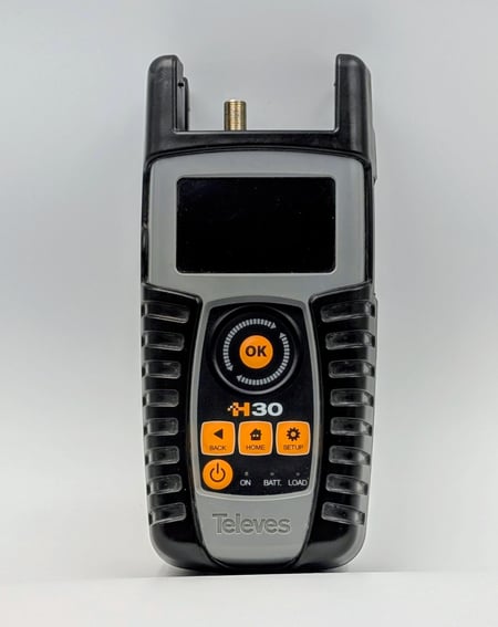
The RF input of the fiber transmitter requires a coaxial cable of RG-6 or equivalent with an "F" type connector. Prior to connecting the coaxial cable, it is recommended to utilize an RF meter such as a Televes 30 to ensure the proper RF input levels.
-
For digital RF signals, the levels should be +20 dBmV flat with an MER above 40dB. If you have less than 8 QAM channels then this input requirement needs to be increased to a flat +23-25dBmV. For analog RF signals, the levels should be +25 dBmV flat with an MER above 40dB. After ensuring the proper RF levels, connect the coaxial cable to the RF Input port in the rear of the Fiber Transmitter.
-
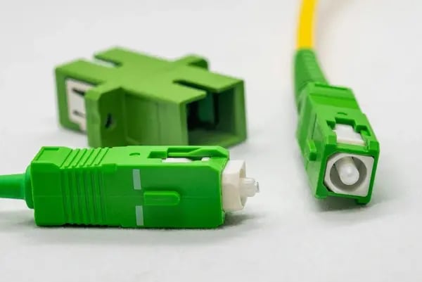
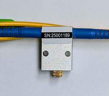
The Optical Signal Output connector requires a Single Mode Angle Polished Fiber (SC/APC: green connector).
-
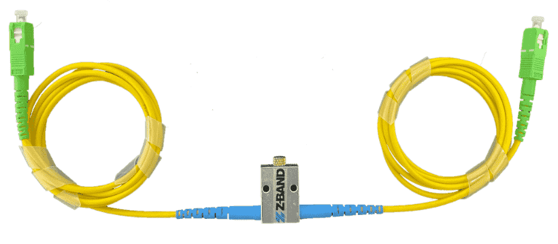
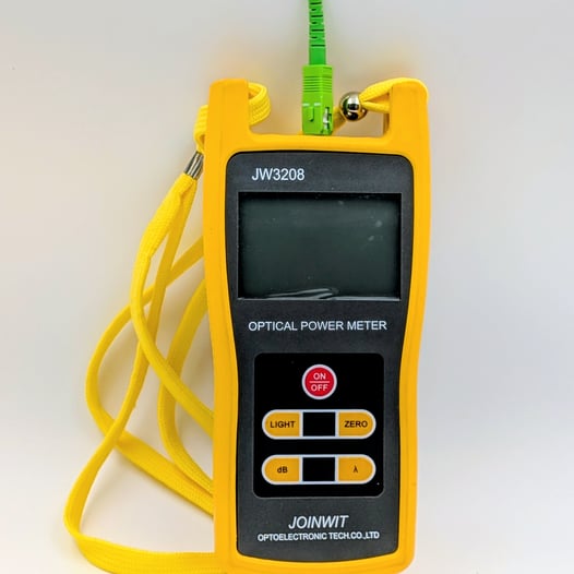
Prior to connecting the fiber cable before first powering up it is recommended to connect a Variable Attenuation Fiber Cable attached to a fiber meter such as a JOINWIT JW3208 to ensure the proper output levels.
-
After connecting the Variable Attenuation Fiber Cable to the meter, connect the two AC power cords to the dual power supplies to the unit and turn both power switches on. Observe the front panel LED status. After the LED working status indicator turns green, the device is working normally. After ensuring both the RF input and Optical Output cables are attached, turn the keyed laser switch on.

-
Adjust the knurled adjustment screw of the Variable Attenuation Fiber Cable counter-clockwise until your reading is -2.0 dBm
-
When the you have a made the proper adjustments, turn off the laser and disconnect the Variable Attenuation Fiber Cable from the fiber meter. Insert the fiber cable into the assigned fiber port or a fiber splitter. You may now turn on the laser or power off the Fiber Transmitter.